Interfacial Thermal Resistance Calculation at a Metal–Polymer Interface
Interfacial Thermal ResistanceSemiconductorAdhesive Materials
Theme Overview
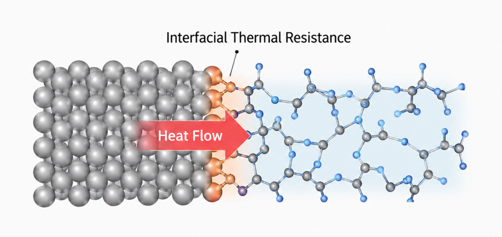
Interfacial thermal resistance is a key property in fields such as semiconductors, power electronics, and batteries, governing heat transport across material combinations from metal–metal to metal–polymer interfaces. As thermal management grows critical in semiconductor back-end (packaging) processes, characterizing the thermal properties of polymers on substrates has drawn particular attention.
Interfacial thermal resistance has traditionally been evaluated with classical force fields, but accurately describing the complex chemical bonding at heterogeneous interfaces is difficult, which has limited predictive accuracy. With Matlantis, the calculation can be performed for any combination of elements while accounting for interfacial adhesion. In this case study, we quantify the interfacial thermal resistance of bonded Au/PMMA and Ni/PMMA interfaces, and present an integrated Matlantis workflow from structure modeling to property calculation.
Computational details
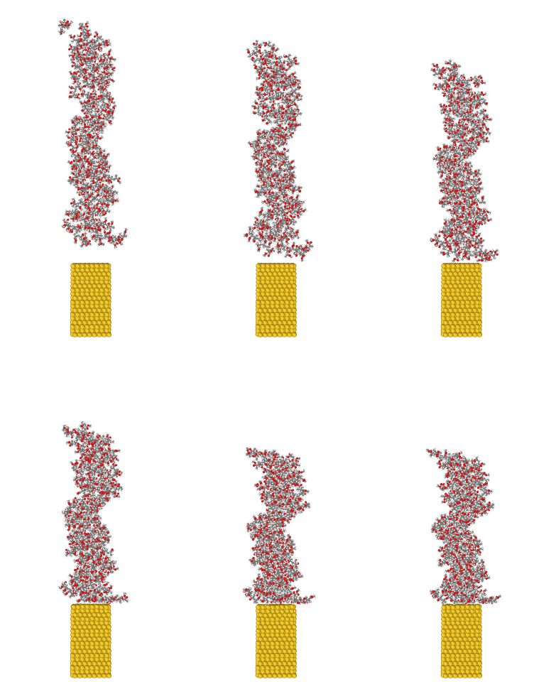
In this work, to speed up the modeling of the bonded structure, we used the coupling between the classical force fields implemented in the molecular simulation software OpenMM and the ASECalculator. Following the procedure below, we built junction models of a metal slab and the polymer (PMMA, 5-mer).
- We ran classical force-field MD until the polymer reached 80% of its target density (the GAFF2 force field for the polymer; metal atoms held fixed; an LJ potential between the polymer and the metal).
- To compute the interfacial adhesion with high accuracy, we switched to a PFP/MM scheme for the remaining 20% of the compression. The PFP region covers the vicinity of the interface, and the MM region covers everything else.
At the PFP/MM boundary, the outside looks like vacuum from PFP's point of view, so we introduced two refinements. On the polymer side, where the boundary cuts covalent bonds, we used the link-atom method to attach a virtual hydrogen atom beyond each cut bond so that PFP sees a physically reasonable bonding environment; these atoms are not used in the MD updates. On the metal side, we placed a buffer layer outside the PFP region that is visible to PFP but held fixed, so that the boundary atoms see bulk metal and experience natural forces. No chemical bonds form between the polymer and the metal at the classical stage, but once the calculation switches to PFP/MM, the two adhere to each other (see Fig. 1).
The calculations were run on a GPU notebook instance available on Matlantis on a trial basis. This accelerates the classical force-field calculation on the GPU and, by reducing the size of the PFP region, shortens its computation as well; as a result, a compression run that could take several days with PFP alone was completed in about 30 minutes. Using this approach, we rapidly built four models in total: Au/PMMA and Ni/PMMA at about 3,000 atoms, and, with a larger cross-section, Au/PMMA and Ni/PMMA at about 7,000 atoms.
Results and Discussion 1
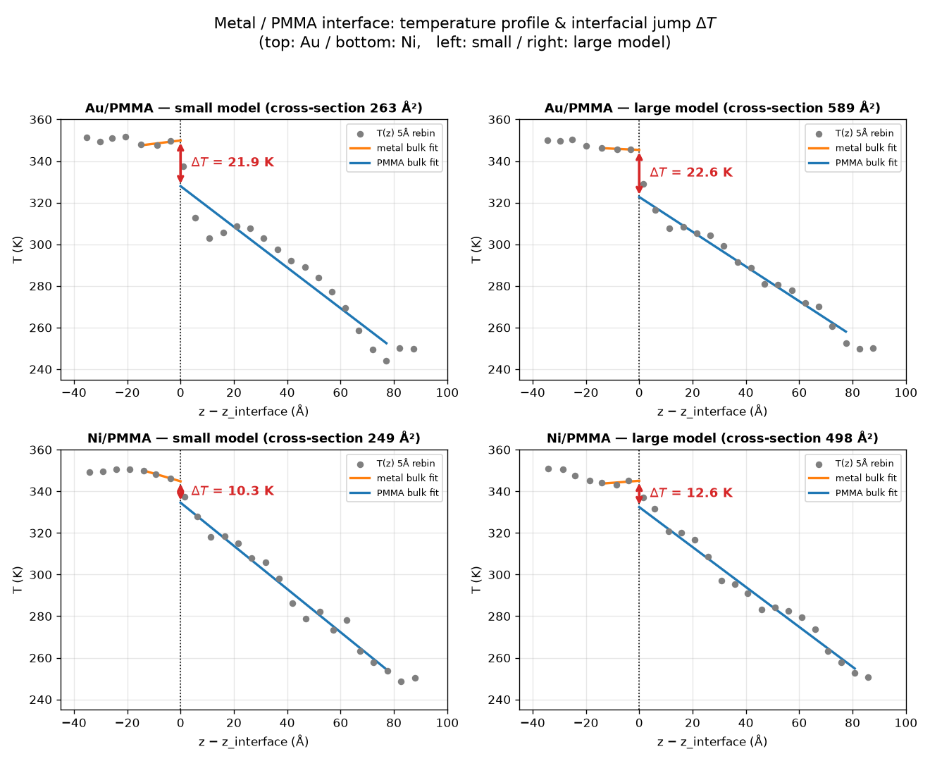
Starting from the bonded structures, we used the Matlantis-LAMMPS interface to equilibrate each model by geometry optimization followed by NPT and NVT runs, and then performed a 500 ps non-equilibrium molecular dynamics (NEMD) simulation with a hot bath (350 K) on the metal side and a cold bath (250 K) on the polymer side. In the NEMD runs, PFP was assigned to all atoms. From the resulting snapshots, we divided the system into a series of thin slabs along the heat-flow direction and defined the temperature of each slab from the kinetic energy of the atoms within it. We then fitted straight lines to the bulk heat-conduction regions on the metal and polymer sides (excluding the thermostat regions) and defined the interfacial temperature jump ΔT as the discontinuity obtained by extrapolating both fits to the interface. The results are shown in Figure 2, from which the following can be read:
– The temperature jump is larger for Au than for Ni (Au ~22 K versus Ni ~10-13 K). This suggests a difference in how well PMMA bonds to each metal. Indeed, Au adsorbs mainly through dispersion interactions, and the resulting restriction of heat transport across the interface can be interpreted as the origin of this difference.
– The small and large models give nearly identical temperature jumps (Au: 21.9 vs 22.6 K; Ni: 10.3 vs 12.6 K). This means that the interfacial property has converged with respect to the lateral cross-sectional size, and suggests that a small model can already provide a reasonable estimate when computation time is a concern.
Results and Discussion 2
We also evaluated the interfacial thermal resistance (Kapitza resistance) for the four models using the following relation:
where J is the heat current across the interface [W] and A is the interfacial cross-sectional area [m2]. The resulting values are summarized in Table 1. The experimental interfacial thermal resistance of Au/PMMA has been reported to be 16.9 × 10⁻⁹m2K/W, and our calculated value is about half of this [1]. Since experimental interfaces contain contamination and roughness whereas our calculation treats a clean, ideal interface, it is a natural consequence that the calculation conducts heat more easily – that is, gives a lower resistance – than the experiment. The same study [1] also reports that inserting a 2 nm Ni layer between Au and PMMA to enhance heat conduction raises the interfacial thermal conductance (the inverse of the interfacial thermal resistance) to 2.4 times that of the bare Au/PMMA interface. Our results are consistent with this finding as well, with the calculated resistance being relatively low for Ni. Note that because the Ni interface has a small resistance and hence a small ΔT, its calculated values carry a larger uncertainty than those for Au.
In summary, we have presented fast interface modeling with OpenMM and the resulting interfacial thermal resistances. Interfacial properties are among the key material properties that pose challenges across a wide range of industries, and Matlantis has the notable strength of handling realistic interfaces without any system-specific tuning. This modeling approach can be applied not only to interfacial thermal resistance calculations but also to interfacial tensile simulations and more, and we look forward to the variety of applications it may enable.
Table 1. Interfacial thermal resistance of Au/PMMA and Ni/PMMA
| Model (Metal/Polymer) | Interfacial Thermal Resistance RK[m² K W⁻¹] |
| Au/PMMA (small) | 7.9 × 10⁻⁹ |
| Au/PMMA (large) | 7.5 × 10⁻⁹ |
| Ni/PMMA (small) | ~ 2 × 10⁻⁹ |
| Ni/PMMA (large) | ~ 5 × 10⁻⁹ |
Calculation conditions
| Calculation conditions | Details |
| PFP model version | v9.0.0 |
| calc_mode | r2scan_plus_d3 |
| System size | Au/PMMA:3,497 atoms/ 7,754 atoms Ni/PMMA:3,703 atoms/ 7,406 atoms |
| Computational time | Modeling: ~30 min (using a Matlantis GPU notebook) NEMD: ~2 days (small models), ~4 days (large models) |
| MD conditions | Simulation time = 500 ps, timestep = 1 fs |
| Temperature | Hot bath (metal side): 350 K, cold bath (polymer side): 250 K |
| Ensemble | Equilibration: geometry optimization → NPT → NVT (300K) Production (NEMD): NVE + Langevin thermostats on the bath regions only |
References
[1] S. Sandell et al., Nanomaterials 10, 670 (2020). https://doi.org/10.3390/nano10040670
Publication date of this case study: 2026.07.13
-


 URL
URL
Copied
what's new
NEW
LightPFPを用いたGaN/AlNヘテロエピタキシャル薄膜のクラック伝播の大規模分子動力学シミュレーション
セラミックス半導体
NEW
Analysis of the Ozone Oxidation Reaction Mechanism of Rubber Antidegradants
PolymerReaction pathway exploration
High-Accuracy, High-Speed Binding Energy Evaluation of Cyclin-Dependent Kinase 2 Inhibitors
Bio and Pharma
Data-Driven Method for Discovering Low Adsorption Energy Molecules on Si Surfaces
ScreeningMaterials InformaticsSemiconductors
Calculation and Verification of Methanol Synthesis Catalysts
Methanol synthesis catalystsLarge-scale screening